Operating Room Configuration, Port Placement, and Docking of Robot
Before any procedure, the robot has to be prepared for surgery. It includes the connection of all necessary parts, such as sterile drapes and connectors needed for surgery and the calibration process. These steps are conducted by a core team of scrub nurses specifically trained in handling the robot while the patient is in preparation for surgery. Currently, the only available system for laparoscopic surgery is the da Vinci surgical system, developed by Intuitive Surgical (Sunnyvale, CA, USA).
Any robotic procedure is performed by a team of surgeons and nurses. It includes the console surgeon, patient-side assistant surgeon, and the scrub nurse. Although the console surgeon is the leader of the team, a trained assistant surgeon is of paramount importance as he/she is the person responsible for robot docking, instrument change, manipulation of laparoscopic instruments, application of hemostatic instruments/clips, lavage, and aspiration, specimen extraction, drainage and closure of abdominal wall. A trained scrub nurse is also important in draping the robotic arms, attaching the optics, instrument changes, and undocking of the robot.
Operating Room Configuration
This topic includes the optimum positioning of the following components in the operating room (OR) so as to allow for maximum functionality:
• Surgeon console positioning
• Patient cart positioning
• Vision cart positioning.
Surgeon Console Position
The surgeon console is placed outside of the sterile field. It should be oriented in such a position so that the surgeon has a clear view of the operative field, vision cart, and able to communicate directly with the assistant surgeon and the scrub nurse. For moving or positioning the surgeon console, only the handle on the back of the console is used. It should never be pushed or pulled by the console body or armrest to maneuver the console into place. Wheel locks located on the rear wheels of the surgeon console should be locked after positioning of the console for the surgery.

Patient Cart Positioning
The patient cart is placed in a sterile field. It should be draped in a separate area in the room prior to moving it into place for surgery. This should an area of the room where it will not easily come into contact with nonsterile objects or impede traffic. Once the patient cart is draped, and the patient is positioned, prepared, draped and ports are placed. Then use the patient cart motor drive to help move the cart into the sterile field.
The patient cart brakes are designed to automatically engage when the motor drive is not in use.
Motor Drive Operation
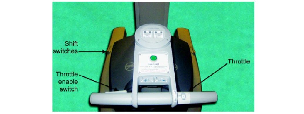
The motor drive interface consists of the following components:
• Throttle
• Throttle enable switch
• Shift switches.
To operate the motor drive:
• Ensure that the patient cart is powered on
• Ensure the shift switches are in the drive position.
• Throttle enables the switch to be held and throttle rotated away from the operator or towards him/her depending on the intended direction of movement.
– The cart power LED will flash green whenever the throttle enables the switch is activated.
– The drive speed of the cart can be controlled by rotating the throttle to a different extent in each direction.
The motor drive will not engage whenever cannulae or instruments are installed on the system. A yellow LED on the motor drive interface labeled “cannula installed: cart drive disabled” will indicate when cannulae or instruments are installed and the motor drive is non-operational. This has been done for safety purposes.
Shift Switches
The patient cart can be moved without the use of the motor drive (for example, during a power loss) by rotating the shift switches (image B) to the neutral (N) position. The cart can then be moved manually. When the cart has been moved, shift switches should be placed in the drive (D) position to set the patient cart brakes.
For patient safety, the shift switches must be kept in the drive (D) position so that the motor drive remains engaged during surgery (image A).

Vision Cart Positioning
The vision cart is placed adjacent to the patient cart, just outside of the sterile field, to allow the patient cart operator to see the component displays.
• The vision cart should be close enough to the patient cart to allow unrestricted camera cable movement during surgery.
• Wheel locks are located on the rear wheels of the vision cart. These should be locked after the cart is positioned for surgery.

Steps of Docking
• Position patient and OR table, including table tilt
• Position patient cart over the patient
• Set patient cart brakes
• Docking the camera arm
• Docking the instrument arms
• Check system set-up.
The patient table should be positioned according to surgeon preference (depending on the contemplated procedure) before docking the robotic arms. Once the arms are docked to the ports and instruments placed, the patient position should not be changed. The pneumoperitoneum is created and the ports inserted by either the lead surgeon or the patient side assistant surgeon.
Port Placement
The port positions vary from patient-to-patient, the procedure to procedure, and surgeon-to-surgeon. It is very difficult to form guidelines specific position of ports but broad guidelines are framed to maximize the endoscopic view, instrument reach and to minimize external arm clashing.
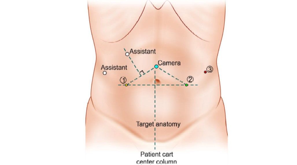
The camera port is inserted keeping the following principles in mind:
• Should be in line with the target anatomy (TA)
• Should be at 10 to 20 cm distance from the TA
• Should be in line with the center column of the patient cart. Diagnostic laparoscopy is done after insertion of the camera port to look for safe entry, any adhesions, and surgical feasibility.
A disposable 12 mm trocar cannula assembly is used as the camera port. There are specialized camera arm cannula mounts (on the patient cart camera arm) corresponding to each validated third-party cannula.

Working Ports
8 mm da Vinci ports are inserted for robotic arms are inserted keeping in mind the following principles:
• > 8 cm distance between the da Vinci ports (image A).
• 10 to 20 cm distance should be maintained between the dV ports and target anatomy (image B).
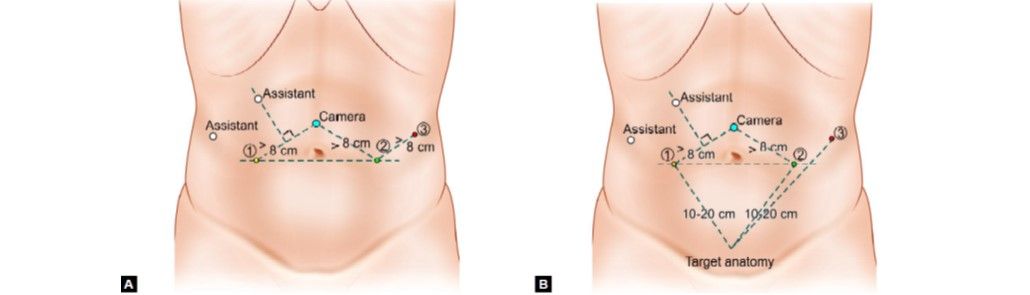
10 cm distance from TA is good but 20 cm distance is better. Ports placed closed to the target anatomy impedes the view of the surgical site and makes the operation technically challenging. Conversely, ports placed > 20 cm from TA makes it difficult to see or reach with robotic instruments. Assistant port if needed is inserted 5 to 10 cm away from the da Vinci ports in the desired position. 5 or 10 mm ports can be used according to the intended function of the port. da Vinci provides 8 mm reusable cannulas with disposable seals for the robotic arms. They come with a bladeless obturator for insertion.
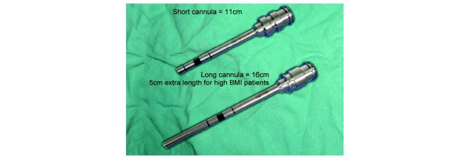
These come in two lengths:
1. Short (11 cm cannula)
2. Long (16 cm cannula) for high BMI patients.
Remote Center Technology
The remote center is the fixed point in the space around which the surgical arm and cannula move. It helps in maneuvering instruments/endoscopes in the surgical site while exerting minimal force on the abdominal or thoracic wall. It is marked on the da Vinci cannulae at a point to minimize stress to the patient. The remote center can be adjusted on the patient side at the patient cart using the clutch button.

Positioning the Patient Cart
Once the patient is positioned and the ports are inserted, it is time to attach patient cart instrument arms to the patient in a process called docking. Before moving the patient cart into position over the patient, it is important to align the OR table and the patient. Then push the patient cart over the patient using the motor drive on the cart.
Motor drive can be used in integrated mode when the patient cart is connected to the rest of the system or in standalone mode as well. The shift switches on the base of the patient cart need to be set in drive (D) position. Then the cart can be moved by pressing the throttle to enable switch and throttling either forwards or backward. It can be moved manually if the shift switch is set in a neutral (N) position.


Two people should be used to move the cart, one pushes or pulls the cart and the second person verbally directs regarding the direction of movement. When the cart is in position, the shift switch should be set to drive position (D) for locking the cart. Installing the camera or instrument arm locks the patient cart automatically for patient safety.
Care should be taken to align the camera port, target anatomy, and the center column.

Docking the Camera Arm
The camera arm should be docked first after positioning the patient cart. Align the camera port, target anatomy, and the center column of the patient cart. Use the clutch button to change the angle of the camera arm to match the angle of the cannula so that it points to the target anatomy.

Stabilize the cannula at the port site with one hand pointing it towards the target anatomy. Bring cannula into the cannula mount on the camera arm and clip both wings shut to hold the cannula in place.

Camera arm set-up joint # 2 is placed opposite the instrument arm 3. Set-up joints are numbered starting from the joint closest to the center column. Setting the system in this position allows maximum range of motion for all instrument arms. There is a thick blue line and a blue arrow on set-up joint # 2 on the camera arm indicating the sweet spot. Sweet spot should be aligned by lining up the blue arrow within the boundaries of blue line. Setting sweet spot gives patient cart arms maximum range of motion ensuring instrument and endoscope reach of all parts of target anatomy. Remember that overextending or not extending the camera arm enough will limit the instrument range of motion. Align the camera arm clutch button, 3rd set-up joint and the center column. Strive to maintain the sweet spot and alignment of the camera arm throughout the docking process.


Docking of Instrument Arms
After docking the camera arm, instrument arms are positioned in place so as to allow the maximum range of motion of the arms. It is done in the following steps:
• Position the instrument arm with the arm number and sterile adaptor facing forwards.

• Allow approximately 45° angle between each arm. Note that the position of instrument arm 3 can vary according to the patient body habitus and the procedure. After positioning, ensure that the arms will not collide with the patient or interfere with each other.

• Dock the instrument arms by bringing them to the cannula using the port clutch button. Bring the instrument arm to the cannula and lock the wings of the quick click cannula mount on the arm to clip the arm to the cannula.

Confirm that the remote center of the port is present at the desired place in the abdominal wall. Remember to stabilize the cannula with one hand at the port site while docking the instrument arm.
Check System Set-up
After docking the instrument arms, check the arm set-up. Start by confirming that the sweet spot of the camera arm is in the right position (i.e. arrow is pointing towards the thick blue line). If needed, move the arm back into position taking care to stabilize the cannula at the port site.
Next, check the alignment of the camera port, target anatomy, and the center column of the patient cart.
Now check the instrument arm set-up. Separate the instrument arms to maximize the range of motion. Check the set-up joint angles to minimize potential collisions. The angle at the set-up joint 2 should be approximately 90°.


Endoscope Insertion and Removal
First, insert the endoscope into the cannula keeping the intuitive logo on the camera head facing the camera arm. Place the body of the endoscope into the camera arm sterile adaptor making sure that the body of the endoscope is fully connected. Give it a gentle turn to ensure it is locked in place.


Push the endoscope into the cannula by pressing the camera arm clutch button till it is past the cannula tip towards the target anatomy. Press the clutch button again to lock the camera assembly into place.
To remove the endoscope, remove the camera cables from the clip on the camera arm. Then unlock the endoscope by opening the two latches on the camera arm sterile adaptor. Then remove the endoscope.
Instrument Insertion
Begin by straightening the instrument tip. Insert the instrument into the cannula. Slide the instrument housing into the sterile adaptor sandwiching the instrument housing and the instrument arm between both hands. Press the arm clutch button and push the instrument into the surgical field, keeping the tip under endoscopic vision.


Instrument Removal and Guided Tool Change
For removing the instruments, the surgeon should straighten the instrument tip and open the jaws of the instrument to ensure it does not hold any tissue. Then press the release levers on the instrument housing and simply pull off the instrument.

Removal of the instrument should be done with the utmost care and with complete knowledge of the operating surgeon so as to prevent any inadvertent injury to the tissues.
Guided Tool Change
This feature helps in aligning a new instrument in the same position as the previous one removed. It adapts the replaced instrument tip just short of the position of the previously placed instrument tip.
When this feature is activated, the LEDs on the instrument arm alternately blink white and green. Just push the instrument with one finger and guided tool change (GTC) will guide it into the correct position. Stop as soon as you encounter any resistance.

This function is disabled when there is a change in the position of the instrument arm during changing the instrument. This is because the position memory of the instrument arm is reset when the position is changed.
Before any procedure, the robot has to be prepared for surgery. It includes the connection of all necessary parts, such as sterile drapes and connectors needed for surgery and the calibration process. These steps are conducted by a core team of scrub nurses specifically trained in handling the robot while the patient is in preparation for surgery. Currently, the only available system for laparoscopic surgery is the da Vinci surgical system, developed by Intuitive Surgical (Sunnyvale, CA, USA).
Any robotic procedure is performed by a team of surgeons and nurses. It includes the console surgeon, patient-side assistant surgeon, and the scrub nurse. Although the console surgeon is the leader of the team, a trained assistant surgeon is of paramount importance as he/she is the person responsible for robot docking, instrument change, manipulation of laparoscopic instruments, application of hemostatic instruments/clips, lavage, and aspiration, specimen extraction, drainage and closure of abdominal wall. A trained scrub nurse is also important in draping the robotic arms, attaching the optics, instrument changes, and undocking of the robot.
Operating Room Configuration
This topic includes the optimum positioning of the following components in the operating room (OR) so as to allow for maximum functionality:
• Surgeon console positioning
• Patient cart positioning
• Vision cart positioning.
Surgeon Console Position
The surgeon console is placed outside of the sterile field. It should be oriented in such a position so that the surgeon has a clear view of the operative field, vision cart, and able to communicate directly with the assistant surgeon and the scrub nurse. For moving or positioning the surgeon console, only the handle on the back of the console is used. It should never be pushed or pulled by the console body or armrest to maneuver the console into place. Wheel locks located on the rear wheels of the surgeon console should be locked after positioning of the console for the surgery.
Surgeon console handle
Patient Cart Positioning
The patient cart is placed in a sterile field. It should be draped in a separate area in the room prior to moving it into place for surgery. This should an area of the room where it will not easily come into contact with nonsterile objects or impede traffic. Once the patient cart is draped, and the patient is positioned, prepared, draped and ports are placed. Then use the patient cart motor drive to help move the cart into the sterile field.
The patient cart brakes are designed to automatically engage when the motor drive is not in use.
Motor Drive Operation
The motor drive interface consists of the following components:
• Throttle
• Throttle enable switch
• Shift switches.
Location of the throttle, throttle enable switch, and shift switches
To operate the motor drive:
• Ensure that the patient cart is powered on
• Ensure the shift switches are in the drive position.
• Throttle enables the switch to be held and throttle rotated away from the operator or towards him/her depending on the intended direction of movement.
– The cart power LED will flash green whenever the throttle enables the switch is activated.
– The drive speed of the cart can be controlled by rotating the throttle to a different extent in each direction.
The motor drive will not engage whenever cannulae or instruments are installed on the system. A yellow LED on the motor drive interface labeled “cannula installed: cart drive disabled” will indicate when cannulae or instruments are installed and the motor drive is non-operational. This has been done for safety purposes.
Shift Switches
The patient cart can be moved without the use of the motor drive (for example, during a power loss) by rotating the shift switches (image B) to the neutral (N) position. The cart can then be moved manually. When the cart has been moved, shift switches should be placed in the drive (D) position to set the patient cart brakes.
For patient safety, the shift switches must be kept in the drive (D) position so that the motor drive remains engaged during surgery (image A).
(A) Drive motor engaged; (B) Drive motor disengaged
Vision Cart Positioning
The vision cart is placed adjacent to the patient cart, just outside of the sterile field, to allow the patient cart operator to see the component displays.
• The vision cart should be close enough to the patient cart to allow unrestricted camera cable movement during surgery.
• Wheel locks are located on the rear wheels of the vision cart. These should be locked after the cart is positioned for surgery.
Position of vision cart
Steps of Docking
• Position patient and OR table, including table tilt
• Position patient cart over the patient
• Set patient cart brakes
• Docking the camera arm
• Docking the instrument arms
• Check system set-up.
The patient table should be positioned according to surgeon preference (depending on the contemplated procedure) before docking the robotic arms. Once the arms are docked to the ports and instruments placed, the patient position should not be changed. The pneumoperitoneum is created and the ports inserted by either the lead surgeon or the patient side assistant surgeon.
Port Placement
The port positions vary from patient-to-patient, the procedure to procedure, and surgeon-to-surgeon. It is very difficult to form guidelines specific position of ports but broad guidelines are framed to maximize the endoscopic view, instrument reach and to minimize external arm clashing.
The camera port is inserted keeping the following principles in mind:
• Should be in line with the target anatomy (TA)
• Should be at 10 to 20 cm distance from the TA
• Should be in line with the center column of the patient cart. Diagnostic laparoscopy is done after insertion of the camera port to look for safe entry, any adhesions, and surgical feasibility.
A disposable 12 mm trocar cannula assembly is used as the camera port. There are specialized camera arm cannula mounts (on the patient cart camera arm) corresponding to each validated third-party cannula.
Camera port positioning
(A) Disposable 12 mm trocar cannula assembly for camera port; (B) Camera port is mounted on the camera arm
Working Ports
8 mm da Vinci ports are inserted for robotic arms are inserted keeping in mind the following principles:
• > 8 cm distance between the da Vinci ports (image A).
• 10 to 20 cm distance should be maintained between the dV ports and target anatomy (image B).
Port placement
10 cm distance from TA is good but 20 cm distance is better. Ports placed closed to the target anatomy impedes the view of the surgical site and makes the operation technically challenging. Conversely, ports placed > 20 cm from TA makes it difficult to see or reach with robotic instruments. Assistant port if needed is inserted 5 to 10 cm away from the da Vinci ports in the desired position. 5 or 10 mm ports can be used according to the intended function of the port. da Vinci provides 8 mm reusable cannulas with disposable seals for the robotic arms. They come with a bladeless obturator for insertion.
These come in two lengths:
1. Short (11 cm cannula)
2. Long (16 cm cannula) for high BMI patients.
da Vinci cannula
Remote Center Technology
The remote center is the fixed point in the space around which the surgical arm and cannula move. It helps in maneuvering instruments/endoscopes in the surgical site while exerting minimal force on the abdominal or thoracic wall. It is marked on the da Vinci cannulae at a point to minimize stress to the patient. The remote center can be adjusted on the patient side at the patient cart using the clutch button.
Remote center technology
Positioning the Patient Cart
Once the patient is positioned and the ports are inserted, it is time to attach patient cart instrument arms to the patient in a process called docking. Before moving the patient cart into position over the patient, it is important to align the OR table and the patient. Then push the patient cart over the patient using the motor drive on the cart.
Motor drive can be used in integrated mode when the patient cart is connected to the rest of the system or in standalone mode as well. The shift switches on the base of the patient cart need to be set in drive (D) position. Then the cart can be moved by pressing the throttle to enable switch and throttling either forwards or backward. It can be moved manually if the shift switch is set in a neutral (N) position.
Shift switch
Throttle with throttle enable switch
Two people should be used to move the cart, one pushes or pulls the cart and the second person verbally directs regarding the direction of movement. When the cart is in position, the shift switch should be set to drive position (D) for locking the cart. Installing the camera or instrument arm locks the patient cart automatically for patient safety.
Care should be taken to align the camera port, target anatomy, and the center column.
Alignment of camera arm, target anatomy, and center column of patient cart
Docking the Camera Arm
The camera arm should be docked first after positioning the patient cart. Align the camera port, target anatomy, and the center column of the patient cart. Use the clutch button to change the angle of the camera arm to match the angle of the cannula so that it points to the target anatomy.
Docking the camera arm
Stabilize the cannula at the port site with one hand pointing it towards the target anatomy. Bring cannula into the cannula mount on the camera arm and clip both wings shut to hold the cannula in place.
Mounting cannula to camera arm
Camera arm set-up joint # 2 is placed opposite the instrument arm 3. Set-up joints are numbered starting from the joint closest to the center column. Setting the system in this position allows maximum range of motion for all instrument arms. There is a thick blue line and a blue arrow on set-up joint # 2 on the camera arm indicating the sweet spot. Sweet spot should be aligned by lining up the blue arrow within the boundaries of blue line. Setting sweet spot gives patient cart arms maximum range of motion ensuring instrument and endoscope reach of all parts of target anatomy. Remember that overextending or not extending the camera arm enough will limit the instrument range of motion. Align the camera arm clutch button, 3rd set-up joint and the center column. Strive to maintain the sweet spot and alignment of the camera arm throughout the docking process.
Camera arm set-up joint #2 facing opposite instrument arm 3
Sweet spot and its alignment
Alignment of camera arm clutch button, 3rd set-up joint, and the center column
Docking of Instrument Arms
After docking the camera arm, instrument arms are positioned in place so as to allow the maximum range of motion of the arms. It is done in the following steps:
• Position the instrument arm with the arm number and sterile adaptor facing forwards.
The positioning of the instrument arm
• Allow approximately 45° angle between each arm. Note that the position of instrument arm 3 can vary according to the patient body habitus and the procedure. After positioning, ensure that the arms will not collide with the patient or interfere with each other.
Alignment of instrument arms with respect to camera arm and each other
• Dock the instrument arms by bringing them to the cannula using the port clutch button. Bring the instrument arm to the cannula and lock the wings of the quick click cannula mount on the arm to clip the arm to the cannula.
Example of mounting instrument arm on to the cannula
Confirm that the remote center of the port is present at the desired place in the abdominal wall. Remember to stabilize the cannula with one hand at the port site while docking the instrument arm.
Check System Set-up
After docking the instrument arms, check the arm set-up. Start by confirming that the sweet spot of the camera arm is in the right position (i.e. arrow is pointing towards the thick blue line). If needed, move the arm back into position taking care to stabilize the cannula at the port site.
Next, check the alignment of the camera port, target anatomy, and the center column of the patient cart.
Now check the instrument arm set-up. Separate the instrument arms to maximize the range of motion. Check the set-up joint angles to minimize potential collisions. The angle at the set-up joint 2 should be approximately 90°.
Relative positions of the instrument arms
The right angle at set-up joint 2

Depiction of the correct method of docking of patient cart
Endoscope Insertion and Removal
First, insert the endoscope into the cannula keeping the intuitive logo on the camera head facing the camera arm. Place the body of the endoscope into the camera arm sterile adaptor making sure that the body of the endoscope is fully connected. Give it a gentle turn to ensure it is locked in place.
Endoscope insertion into camera arm sterile adaptor of the camera arm
Next, secure the camera cable using the camera cable clip and drape the cable across the instrument arm.
Camera cable clip highlighted
Push the endoscope into the cannula by pressing the camera arm clutch button till it is past the cannula tip towards the target anatomy. Press the clutch button again to lock the camera assembly into place.
To remove the endoscope, remove the camera cables from the clip on the camera arm. Then unlock the endoscope by opening the two latches on the camera arm sterile adaptor. Then remove the endoscope.
Instrument Insertion
Begin by straightening the instrument tip. Insert the instrument into the cannula. Slide the instrument housing into the sterile adaptor sandwiching the instrument housing and the instrument arm between both hands. Press the arm clutch button and push the instrument into the surgical field, keeping the tip under endoscopic vision.
Inserting the instrument into the cannula

Sliding the instrument into a sterile adaptor on the instrument arm
If there is any resistance while inserting the instrument, one should stop and check for the reason. When the LED lights turn blue, the surgeon can take control of the instrument and start operating.Sliding the instrument into a sterile adaptor on the instrument arm
LED turning blue indicating proper insertion
Instrument Removal and Guided Tool Change
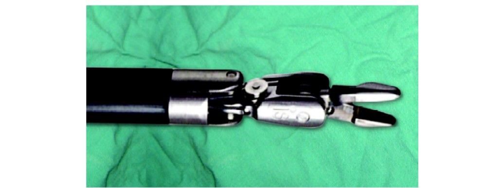
For removing the instruments, the surgeon should straighten the instrument tip and open the jaws of the instrument to ensure it does not hold any tissue. Then press the release levers on the instrument housing and simply pull off the instrument.
Straightening the instrument tip and opening of jaws of the instrument before removal
Pressing the levers to remove the instrument
Removal of the instrument should be done with the utmost care and with complete knowledge of the operating surgeon so as to prevent any inadvertent injury to the tissues.
Guided Tool Change
This feature helps in aligning a new instrument in the same position as the previous one removed. It adapts the replaced instrument tip just short of the position of the previously placed instrument tip.
When this feature is activated, the LEDs on the instrument arm alternately blink white and green. Just push the instrument with one finger and guided tool change (GTC) will guide it into the correct position. Stop as soon as you encounter any resistance.
LED blinking alternately white and green indicating activation of guided tool change

Pushing the instrument with one finger
This function is disabled when there is a change in the position of the instrument arm during changing the instrument. This is because the position memory of the instrument arm is reset when the position is changed.